
No products in the cart.
How to Set Up AS5048B Encoders on a SimpleBGC32 Gimbal
By the AT Group OÜ engineering team · Last updated: 19 November 2026
To use AS5048B encoders with a SimpleBGC32 controller, load the encoder firmware and fit an encoder on every motor. Give each encoder its I²C address: 0x40 for roll, 0x41 for pitch, 0x42 for yaw. Enter the exact pole count in the Hardware tab, then run CALIB.EL FIELD and CALIB. OFFSET. The gearing ratio should read close to 1.0.
This guide follows BaseCam’s manual Using encoders with the SimpleBGC 32 controllers (version 0.19, October 2026) and the ams AS5048 datasheet. Every step links to its source.
Key facts at a glance
- The encoder firmware needs an encoder on every motor. You cannot run one axis with an encoder and two without. A single encoder on yaw only works on the regular firmware from version 2.56. [1]
- AS5048B connects over I²C or PWM, and AS5048A over SPI or PWM. PWM gives 12-bit resolution instead of 14-bit. [1]
- AS5048B does not work with the “High speed I²C” option in the SimpleBGC GUI. [1]
- With encoders, the motors run in field-oriented control (FOC). Current is close to zero when the camera is balanced. [1]
- The AS5048 chip has 14-bit resolution (0.0219° per step) and runs from 3.3 V or 5 V. [3]
Why add encoders to a gimbal?

An encoder tells the controller the exact angle of each motor relative to the frame. BaseCam lists these benefits: [1]
- Motors no longer lose synchronisation or skip steps.
- The controller knows the full camera position relative to the frame. BaseCam says this works better than a second IMU and makes the second IMU unnecessary.
- Power consumption can drop significantly, because the motors are driven with field-oriented control.
- Instant torque increases for the same reason.
- The system can measure camera balance, which enables automatic balancing with extra servos and moving counterweights.
- You can move the camera by hand to a new position.
- Stabilisation precision improves, and the gimbal can compensate faster rotation.
Encoders do not remove jitter caused by motor cogging. If jitter comes from the motor itself, BaseCam suggests a motor with less cogging, a lower pole count, or a uniform O-ring magnet. [1]
AS5048A or AS5048B: which one do you need?
Both chips are 14-bit on-axis magnetic encoders. The difference is the interface: AS5048A has SPI, AS5048B has I²C, and both have a PWM output. [3] SimpleBGC32 supports them like this: [1]
| Encoder | “Regular” boards (Regular, Tiny) | “Extended” boards (Extended, Extended Long, Pro, CAN_MCU) | CAN_Drv / I2C_Drv |
|---|---|---|---|
| AS5048A | PWM, SPI | PWM, SPI | SPI |
| AS5048B | PWM, I²C | PWM, I²C | I²C, address 0x40 |
For most builds, AS5048B over I²C is the simpler choice. The encoders share the I²C line with the IMU sensor, and each one gets its own address, so no extra SPI wiring is needed. [1]

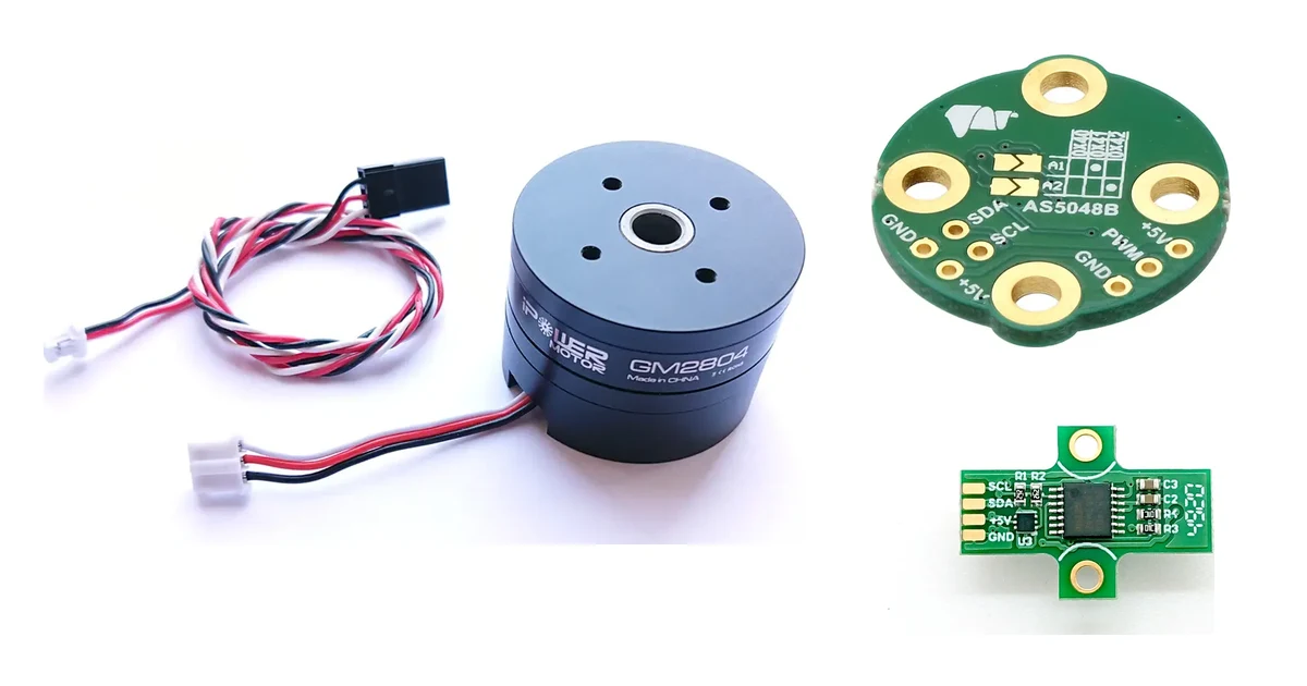
BaseCam makes two AS5048B boards: [2]
- AS5048B on-axis magnetic encoder: 23.3 × 25.8 mm, 1.48 g, with mounting holes at 16 mm and 19 mm spacing. It fits small and mid-size gimbal motors and comes with a 6 × 2.5 mm magnet.
- AS5048B Encoder (iFlight compatible): a 0.70 g board shaped to fit the removable housing of iFlight motors. Use non-metallic or non-magnetic screws with it.

If you want the motor and encoder as one part, the GBM2804H-100T with Encoders comes with either an AS5048A or an AS5048B encoder. It has a 12N14P configuration, a 6 mm hollow shaft, and suits cameras from 150 to 500 g.
Which firmware and boards support encoders?
Every SimpleBGC32 controller can run both the regular and the encoder-enabled firmware. [1] Controllers bought before July 2020 may need a licence change first, which BaseCam handles on its encoders page. [1]
Two rules matter when you plan the build: [1]
- Encoder firmware means encoders on all three axes. A mixed setup is not supported.
- “Extended” and “Pro” boards have dedicated encoder inputs. On “Regular” and “Tiny” boards, the SPI and PWM encoder pins are shared with other inputs. In the encoder firmware, the RC_ROLL input functions (RC PWM, Sum-PPM and Serial Rx) move to AUX3.
We supply both board families: SimpleBGC 32bit Extended and SimpleBGC 32bit Tiny.
How do you mount the encoder and magnet?
The encoder chip sits under a diametrically magnetised (two-pole) magnet fixed to the motor’s shaft cup. [1][3] The datasheet sets the limits: [3]
- Magnet: typically 6–8 mm in diameter and at least 2.5 mm high. The field at the chip must be 30–70 mT.
- Centring: the magnet axis should be within 0.25 mm of the chip centre. Larger magnets allow about 0.5 mm.
- Air gap: typically 0.5–2.5 mm between magnet and chip, with the recommended 6 × 3 mm magnet.
You do not need to align the magnet’s zero position mechanically. The zero point is set in software. [3] Keep soft iron away from the encoder: it bends the field and makes the reading non-linear. [1]

How do you set the I²C address and wire the encoder?
Each AS5048B on the I²C bus needs its own address, chosen by the motor it sits on: [1]
| Axis | I²C address | A1 | A2 |
|---|---|---|---|
| Roll | 0x40 | 0 | 0 |
| Pitch | 0x41 | HIGH | 0 |
| Yaw | 0x42 | 0 | HIGH |
On BaseCam’s board you set the address with solder jumpers. [2] You can also reassign an address to an axis later in the GUI. [1]
Wiring notes: [1]
- I²C: connect the encoder (GND, +5V, SDA, SCL) in parallel with the I²C IMU sensor. This works on all board versions.
- PWM: possible, but it drops to 12-bit and can be less precise. If you use PWM, place the zero-crossing point far from the gimbal’s normal working angles, because the signal can jump between 0% and 100% there.
- SPI (AS5048A): for cables longer than 30 cm, add 33–60 Ω series resistors on SCK and MOSI at the board side and on MISO at the encoder side.
How do you check the encoders in the SimpleBGC GUI?
- Connect the GUI to the controller running encoder firmware.
- In the Encoders tab, select the encoder type, write the settings and restart the controller.
- Open the Monitoring tab. If everything is connected, you will see raw encoder data (ENC_RAW_xx) for each axis.
- For diagnostics, open the Debug tab and request the system state. It shows an error count for each encoder. “DISABLED” means the start-up check failed, usually because of wiring or a dead encoder. [1]
How do you calibrate the encoders?
Calibration has two parts: the electrical field offset and the angle offset. [1]
1. Calibrate the electrical angle offset (CALIB.EL FIELD)
- Balance the camera well. Good balance matters for a good calibration.
- Enter the exact number of poles for each motor in the Hardware tab. Auto-detection can be wrong. A 12N14P motor such as the GBM2804H-100T has 14 magnet poles.
- Check that each encoder gives correct data and is assigned to the right axis.
- Reset all calibration values in the Encoders tab to zero.
- Power on the gimbal in its normal position, with frame and camera level.
- Tune the PID until there are no oscillations or jitter. High precision is not needed yet.
- Disable “Follow” mode and any RC control.
- Press CALIB.EL FIELD. On firmware after 2.60, hold the frame still; the motors calibrate one after another.
- Check that “Encoder/motor gearing ratio” is 1.0 or very close. A large difference triggers an “Emergency stop” and usually means the pole count is wrong.
After this step the motors run in FOC mode. Current is close to zero when the system is balanced, so you can raise the POWER parameter much higher without overheating. Use Heating factor and Cooling factor to limit current during a long stall. [1]
2. Calibrate the angle offset (CALIB. OFFSET)
- Align the camera to its normal position, where every motor is at zero angle to the frame.
- Press CALIB. OFFSET. The current encoder angles become the zero offset and are saved to EEPROM.
- The white arrows on the GUI gauges now show each motor’s angle and should point up in the home position. [1]
Before you ship a gimbal, save a copy of its settings: Board → Backup manager. If you build identical gimbals, the calibration can be reused only when the motor and encoder are mounted exactly the same way. [1]
Troubleshooting
| Symptom | Likely cause | What to do |
|---|---|---|
| “DISABLED” in the Debug tab | Start-up check failed | Check wiring, address and encoder type [1] |
| “Wrong gearing ratio” error | Encoder data inconsistent or on the wrong axis | In Monitoring, ENC_RAW_xx should change by 16384 per full motor turn on the right axis [1] |
| Gearing ratio far from 1.0, or torque drops away from neutral | Wrong pole count, or non-linear reading | Enter the pole count by hand. Check magnet centring and remove nearby soft iron [1] |
| Low torque after calibration | Heating-cooling model is limiting current | Set Heating factor and Cooling factor to 0, then recalibrate if needed [1] |
| Jitter at medium speeds | Motor cogging (not an encoder issue) | Choose a motor with less cogging or fewer poles [1] |
Quick linearity test: rotate the motor by hand by 45° and then 90°. The raw value should change by 2048 and 4096 counts. [1]
Frequently asked questions
Can I use an encoder on the yaw axis only?
Yes, on the regular firmware from version 2.56, without the encoder licence. The encoder then only reads the motor angle; motor control does not change. [1]
Is PWM as good as I²C for the AS5048B?
No. PWM gives 12-bit resolution instead of 14-bit and can be less precise. Use I²C where you can. [1]
What motor winding resistance works best with encoders?
BaseCam recommends lower resistance than typical gimbal motors. For regular SimpleBGC32 boards, 5–10 Ω is good; for more powerful boards, 3–10 Ω. [1]
Do I need high encoder resolution?
Not for stabilisation. BaseCam says 14 bits is enough, because the encoders are not used in a closed loop. Good linearity matters more, especially with high pole-count motors. [1]
BaseCam encoders and gimbal motors in Europe
AT Group OÜ is an official BaseCam distributor in Europe. We supply the AS5048B encoder, the iFlight-compatible AS5048B, the GBM2804H-100T with Encoders and the plain GBM2804H-100T. For heavier cameras there are the GBM5208-200T (800–1550 g) and the GBM110-150T (5–8 kg). See all encoders.
Request a quote → Send us your camera weight and axis layout, and we will match motors, encoders and a SimpleBGC32 board.
Sources
- BaseCam Electronics — Using encoders with the SimpleBGC 32 controllers, v0.19 (5 Oct 2026): https://www.basecamelectronics.com/files/SimpleBGC_32bit_Encoders.pdf
- BaseCam Electronics — On-Axis Magnetic Encoders: https://basecamelectronics.com/as5048b/
- ams — AS5048A/AS5048B Magnetic Rotary Encoder datasheet, v1-11 (2018): https://cdn.sparkfun.com/assets/e/d/e/1/d/AS5048_DS000298_4-00.pdf